ESP8266
ESP8266 is a wonderful little piece of hardware I stumbled over some months ago. It has gotten a lot of attention since some time back in 2014. Mainly because it is an incredible cheap WiFi module (less than $2 these days). It’s not until recently I’ve had some time to actually look into it. Personally I like to know how things work from bottom up, so that means digging down into electronics and the firmware/software you can either use out of the box or build/construct yourself for ESP8266.
Research
I early on decided that I wanted to know more about the chip and architecture. So far I’ve been doing most research on the components of the ESP8266EX version. The CPU, memory and how it boots.
Hardware
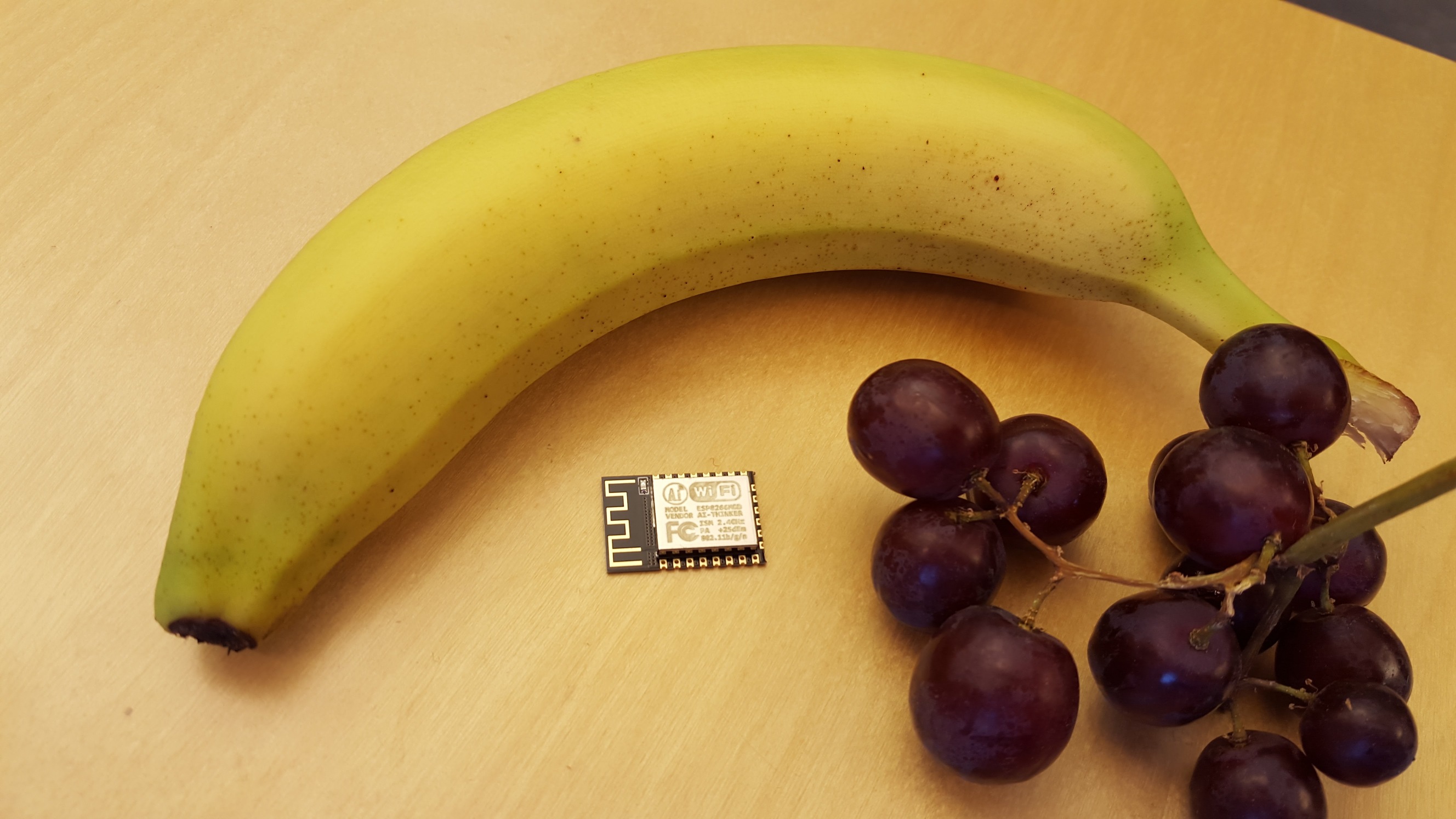
ESP8266(EX) is made by Espressif and there are multiple vendors out there selling different kind of modules embedding it. See this list which are somewhat updated. Personally I’ve bought ESP-01 and ESP-12E and will probably mostly use the latter. ESP-12E is from AI-thinker based on ESP8266EX chip. See Espressifs newest datasheet (0A-ESP8266EX__Datasheet__EN_V4.7_20160225.pdf)
CPU
Espressif is using Tensilica Xtensa in their architecture.
This is a 32bit RISC architecture.
The specific model is L106 also known as lx106.
As far as I understand the architecture doesn’t have any form for CPU cache.
See Max Filippovs crosstool-ng repo for a C/C++ toolchain. You will also need some carefully written linker scripts. An alternative or better option would be to use the esp-open-sdk which bundles the toolchain, Xtensa HAL, esptool and the Espressif SDK. Very handy!
Memory
There is a lot of different conflicting information on the inter tubes. The datasheet doesn’t say a lot about it apart from the fact that it includes SRAM and ROM. Apparently there are separate data and instruction buses, respectively dBus and iBus, + a AHB bus. SRAM nor ROM size is specified explicitly. However, this is said about size in the datasheet:
When ESP8266EX is working under the station mode and is connected to the router, programmable space is accessible to user in heap and data section is 50KB.
Information gathered from the linker scripts and looking at how the stack is setup after boot I’ve concluded:
| Address | Size | Description |
|---|---|---|
| 0x3FFE8000 | 0x14000 | RAM data - Heap |
| 0x3FFEC000 | 0x4000 | RAM data - Stack |
| 0x40000000 | 0x10000 | ROM (incl. bootloader) |
| 0x40100000 | 0x8000 | RAM instructions |
So there should atleast be:
- 96kB data RAM
- 32KB instruction RAM
In addition to this, SPI flash can be mapped to memory through a cache of some sorts. This is used to read instructions directly from flash instead of copying it over to instruction RAM first. Flash cache should be slower than RAM, but I haven’t done any testing myself.
Flash
By using esptool ./esptool.py --port /dev/ttyUSB0 flash_id
my ESP-12E identifies the flash chip:
Manufacturer: e0
Device: 4016
Which I believe is BergMicro BG25Q32 (32Mbit - 4MB).
Electronics
I’ve skipped all the electronics that you probably either already know or should read more about elsewhere. Buying a module like the ESP-12E require you to do a bit of soldering. The inter tubes are full of articles/posts of how to connect your ESP8266 using a breadboard, protoboard or whatever. Google it!
One thing I should mention, that made me hurt for a while, is the fact that when you boot the stock (AT) firmware, ESP8266 draws >200mA. This means that powering it from USB through your USB to serial adaptor will probably NOT work. I learned this the hard way; After a day of cursing and knocking my head against the wall. You are better of using a separate power supply which can handle 500mA @ 3.3V. A capacitor or two across VDD/VCC and ground close to the chip is probably also recommended. I’m an electronics rookie, so if you are having problems, talk to an expert.
UART
There are a couple of things you should know about the serial interface.
- The first stage bootloader initializes UART0 with baud rate based on the external crystal oscillator.
- The stock (AT) firmware and probably others use a baud rate of 115200.
- Booting in UART mode (also known as flashing/programming mode) uses auto sensing baud rate AFAIK.
I’ve experimented with a couple of applications on Linux for serial communication to ESP8266.
I used picocom for a while because it’s pretty straight forward and supports CRLF
which is what you need for executing AT commands using the AT firmware.
Stock picocom doesn’t support custom baud rates.
You would need to build picocom yourself where you enable it.
So reading bootloader messages wouldn’t work out of the box.
The same thing goes for minicom and screen.
You could probably make it work initializing the serial terminal using stty.
As I’m no expert on serial terminals, serial communication drivers nor the
kernel infrastructure for this, I’ve just tried to find whats easiest to use.
I highly recommend using miniterm.py (included in pyserial python package).
miniterm.py /dev/ttyUSB0 74880 for reading the bootloader message and
miniterm.py /dev/ttyUSB0 115200 for anything else unless you want
high speed communication and/or you have firmware that uses something else.
Typical output from the bootloader:
 ets Jan  8 2013,rst cause:2, boot mode:(3,7)

load 0x40100000, len 1396, room 16
tail 4
chksum 0x89
load 0x3ffe8000, len 776, room 4
tail 4
chksum 0xe8
load 0x3ffe8308, len 540, room 4
tail 8
chksum 0xc0
csum 0xc0

2nd boot version : 1.4(b1)
  SPI Speed      : 40MHz
  SPI Mode       : DIO
  SPI Flash Size & Map: 8Mbit(512KB+512KB)
jump to run user1 @ 1000
boot mode:(x,y) gives x = 3 and y = 7 where x is the boot mode.
rst cause:z gives z = 2
| Code | Cause |
|---|---|
| 1 | Normal boot |
| 2 | Reset pin |
| 3 | Software reset |
| 4 | Watchdog reset |
Boot modes
When you reset the ESP8266 it can boot in a couple of different modes.
MTDO |
GPIO0 |
GPIO2 |
Code | Mode | Description |
|---|---|---|---|---|---|
| L | L | H | 1 | UART | Download over UART |
| L | H | H | 3 | Flash | Boot from SPI Flash |
| H | x | x | 4-7 | SDIO | Boot from SD |
L = low
H = high
x = floating
MTDO = GPIO15
MTDO, GPIO0, GPIO2 (3 bit) forms Code.
Whats next?
I’m going to research a bit more to find out how both Flash and UART boot mode actually works. Both modes are already somewhat reverse engineered and documented elsewhere, but it is fun trying to understand and then explain it in a later post. So be sure to check back later for more! :)